 |
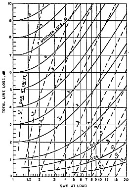
in a transmission line when the SWR is increased (reproduced from the ARRL Antenna Handbook). |
Introduction
In choosing a feeder system for antennas, preference is often give to the use of 50-ohm coaxial cable. This practice is often applied when, in fact, it might be more efficient, or even more convenient, to use balanced open wire lines. This article is devoted to pointing out the advantages of open wire lines and discussing a few particular applications where they might be the preferred choice to feed the antenna.
Coaxial Cable
Before turning to our open wire line discussion, we should first discuss the merits of coaxial cable, in particular the type with polythene dielectric as generally used in amateur radio. Typical values of characteristic impedance for this type of cable are 50 ohms and 75 ohms, very suitable values to match the radiation resistance of many basic antennas. Because of the concentric form of the two cable conductors, the coaxial cable fields are confined to within the inside of the cable bounded by the outer conductor. As there is little field on the outside of the outer conductor, the cable can be mounted directly on a metal support. Owing to this feature and also the flexible nature of the polythene dielectric, the cable is very suitable for running up the side of a metal tower or mast to the antenna on top. Furthermore, radiation directly from the cable is minimised because of the confined field. From a receiving point of view, the cable forms a transmission line which is shielded from direct signal pickup. This is an advantage if the cable must run through a high level field of localised noise.
Attenuation
Figure 1, reproduced from the ARRL Antenna Handbook, compares the attenuation of various types of transmission line. Coaxial cable type RG8 is commonly used to feed an antenna on a rigid structure such as a tower. From the curves, RG8 has an attenuation of 0.8dB per 100ft at 14MHz and 1.2dB per 100ft at 29MHz. This is clearly a very satisfactory cable for HF work but, being a 0.4inch diameter cable, it is somewhat bulky to hang in free space from the average amateur wire antenna. For the wire antenna, we might choose a lighter 0.2-inch diameter cable. Suppose we were to feed a dipole antenna set at a height of half a wavelength above the ground. The radiation resistance at this height could be assumed to be 73 ohms and a 75 ohm 0.2inch cable, such as RG59, could be used to match the antenna through a 1:1 balun transformer at the antenna centre. Referring again to the curves, this cable (RG59) has an attenuation of 1.5dB per 100ft at 14MHz and 2dB per 100ft at 28MHz.
All the attenuation figures we have quoted assume a standing
wave ratio (SWR) of 1:1. We now refer to figure 2 which allows us
to derive the attenuation for SWR greater than 1:1. If our SWR is
3:1, we see that the attenuation of the RG59 cable has increased to
2dB/100ft at 14MHz and 2.8dB/100ft at 28MHz, quite an appreciable
loss. Instead of using RG8, we could use 300 ohm open wire TV line
via a 4:1 impedance ratio balun transformer. This cable is quite
light and flexible, and hangs very well from a wire antenna. From
figure 1, its attenuation for an SWR of 1:1 is around 0.08dB/100ft
at 14MHz and 0.17dB/100ft at 28MHz. We again refer to figure 2 and
it becomes clear that, for an SWR of 3:1, attenuation of the open
wire line is still only a fraction of a dB/100ft at both
frequencies and hence, far more efficient than the coaxial RG59
cable.
|
|
in a transmission line when the SWR is increased (reproduced from the ARRL Antenna Handbook). |
Tuned Feeders
The operation of wire antennas multiband is often made a lot easier if the transmission line can be tuned. This of course implies a very high SWR. Suppose we select a value of SWR = 20, the highest value shown on the curves of figure 2. For this SWR, our RG59 coaxial cable has an attenuation of 6dB/100ft at 14MHz and 7.5dB/100ft at 28MHz. This is excessive attenuation and hence the coax cable is hardly suitable for operation in a tuned feeder mode.
We now apply the SWR = 20 to the open wire TV cable and we get attenuation figures of around 0.8dB/100ft at 14MHz and 0.4dB/100ft at 28MHz. Quite clearly, open wire line is essential for good power efficiency when using tuned feeders.
Some Typical Wire Antennas
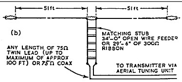
One of the most popular of multi-band wire antennas is the G5RV.
A typical form of this antenna makes use of a 75 ohm twin lead or
coaxial cable coupled via a matching stub of 300 ohm ribbon (refer
figure 3). Whilst a good SWR is achieved at 14MHz, it is reported
to be as high as 6:1 at 7MHz and 21MHz and 4:1 at 28MHz (refer
VK3AVO, AR April 1974 and December 1982). The alternative
arrangement is to use 83ft of open wire line all the way to the
centre of the antenna. Using this type of feed system, the
attenuation is negligible for whatever SWR applies and, hence, it
is the preferred system.
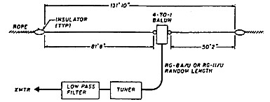
Considerable attention has recently been given in "Random
Radiators" to various forms of the series fed or "Carolina" Windom
antenna. A typical form of this antenna is shown in figure 4. An
antenna impedance of around 200 to 300 ohms is assumed and this is
coupled via a 4:1 or 6:1 impedance ratio balun transformer at the
antenna connecting point. Of course, the balun transformer must be
fitted in some sort of weatherproofing housing attached to the
antenna in space Would it not he better to feed the antenna with
300 ohm TV open wire line (or similar) and fit the balun
transformer in the radio shack? Not only would the transmission
line have lower power loss, but a weatherproof fitting for the
transformer would no longer be required.
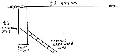
End Fed Horizontal Antennas
If the radio shack is nearer to one end of the wire antenna than
its centre, it is often more convenient to end feed the antenna
with a shorter length of feed line. The end of the antenna is a
high impedance in the order of thousands of ohms, the actual value
being dependent on the wire size and the number of half wavelengths
along the wire. One method of matching this impedance to the lower
impedance of a balanced transmission line is to tap in the line
connection at the appropriate point on a quarter wave matching
stub. (See figure 5). This is an efficient feed system but it is
limited to single band operation.
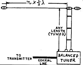
For multi -band operation of the end fed antenna, the open wire
line is fed directly to the antenna end and operated in a tuned
mode. The transmitter is interfaced with the line via a tuner with
balanced output (refer figure 6). The end fed antenna has some
different characteristics to its centre fed counterpart. At a
frequency for which the antenna is one half wavelength long, the
radiation pattern is similar. However, this is not so at higher
multiples of a half wavelength. Take the case of the second
harmonic operation in which the wire is one wavelength long. For
the centre fed antenna, the two half waves are in phase, but for
the end fed antenna, they are out of phase. The centre fed antenna
concentrates its field in a bi-directional pattern whereas the end
fed antenna has four main lobes giving a more omnidirectional
pattern.
An interesting version of the end fed antenna is the end fed inverted V. Assuming this is cut for a half wavelength on 40 metres, it operates similarly to the centre fed inverted V on that band. On 20 metres, there are two half-wave sections as in the horizontal wire but the fields are around 90 degrees to each other (assuming a 90 degree V). In the horizontal plane, the fields are out of phase, but in the vertical plane, they are in phase and additive. It seems reasonable to assume that, on 20 metres, this antenna operates more like a vertical antenna with two broadside elements and a consequent low angle of radiation. The antenna can also be operated as three half waves on 15 metres and four half waves on 10 metres with even more complex radiation patterns. Such an antenna system has been described by Colin Dickman in "Radio ZS" as the "ZS6U Minishack Special". The articles concerned were also reprinted In QST and Amateur Radio.
The end fed inverted V has been used as a multi-band antenna at the writer's home for many years and with considerable success. In this case on 20 metres, the open wire line is matched to the end of the antenna using the quarter wave matching stub. The shorting clip for the stub is just outside the radio shack door and on 40, 15 and 10 metres, the short is removed and the twin open wire line and part of the stub all become the tuned line used on these bands. On 80 metres, the feeder wires are paralleled and the antenna plus feeder and stub become a Marconi antenna operated against ground radials. On this band the radiator is a little over a quarter wave long.
Lengths of Tuned Lines
Tuned lines can be any length provided the antenna tuning system can cope with the impedance reflected down the line. Taking the example of the end fed antenna, odd multiples of a quarter wave will reflect very low impedance and even multiples very high impedance. Both these extreme conditions might present difficulties for the antenna tuning unit and line lengths which are multiples of a quarter wave should perhaps he avoided.
Open Wire Line at VHF
Most custom built VHF antennas are made to match directly into a 50 ohm coaxial cable and, generally speaking, feeding the antenna via a coaxial cable is the most convenient thing to do. Commonly used types of 50 ohm coaxial cable are RG58 and RG8. On two metres, RG58 has an attenuation factor of 4.5dB/100ft and RG8 has a factor of 3dB/100ft. If the transmission line is long, one might well consider open wire line as an alternative to the coax cable. The 300 ohm TV open wire line has an attenuation factor on two metres of only 0.75dB/100ft.
An antenna in common use is the 10 element channel 5A TV Yagi
which has been modified for 2m operation. The active element in
this antenna is a folded dipole which presents a terminal impedance
of around 300 ohms, specifically designed for 300 ohm ribbon cable
or 300 ohm open wire line. Here is a case where the 300 ohm line
can he run all the way to the antenna from the radio shack with
lower loss than using the coaxial cable. At the transmitter end, a
75-300 ohm coaxial balun (as shown in figure 7) can be used to
interface with the transmitter. The 75 ohm load to the transmitter
might be a little high for the usual 50 ohm output but in practice
it can work quite well.
75 ohm coax to 300 ohm open wire (reproduced from the ARRL Antenna Handbook). |
 |
Another antenna which is easily matched to the open wire line is
the J antenna, figure 8. A half wave vertical radiator is connected
at its lower end to a quarter wave matching stub. The open wire
line is simply connected to the stub at an impedance point matching
the line impedance. The position of the connecting taps can be set
by experiment for minimum SWR on the transmission line.
 |
for open wire or other balanced line. |
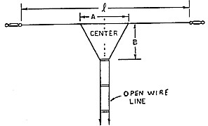
For a horizontal half wave VHF antenna, one might choose to
couple from the open wire line via a delta match as shown in figure
9. This is also a common method of coupling to a HF wire dipole,
which is operated only on its fundamental frequency.
Whilst the open wire TV line provides an ideal low-loss feed system, there is one disadvantage. When it rains, globules of water collect on the bridges which spread the wires and this changes the characteristics of the line. On HF, the water appears to have little effect but, on VHF, the SWR increases quite dramatically. When the rain stops, the water globules can can be shaken from the line with a blow from a broom handle or similar. Once this is done, the SWR returns to normal.
Procurement & Construction
We have given considerable attention to the 300 ohm open wire TV line. This line or or cable is made up of two insulated 18 SWG single strand conductors spaced one half inch (12.7mm) apart. Insulating spacers are moulded around the conductors at intervals of around 12 to 15 cm along the cable. The cable is light and flexible and ideal to hang in space supported at one end by the wire antenna. In the past, the cable has been available from outlets which handle TV antenna components and installation, but of recent years, the supply has dried up. If anyone has information concerning whether it is still available (perhaps from overseas) we would be interested to be informed. Perhaps procurement could be taken up by one of our electronic component suppliers.
Failing supply of a ready made cable, open wire line can be easily constructed. Almost any type of copper wire of fairly heavy gauge (at least 1 mm diameter) will do the job. Single-core wire, rather than stranded wire, makes a more rigid job to keep the two wires parallel. For a given characteristic impedance, the wire spacing depends on the wire gauge used. The relationship between wire spacing, wire diameter and characteristic impedance is as follows:
Impedance Zo = 276 log (2S/d) ohms where S = Centre to centre distance between conductors and d = Diameter of conductor (Same units as S)
With insulating spacers fitted, the actual impedance will be
somewhat lower than that calculated from the formula. Spacers, as
shown in figure 10, can be made up from any suitable low loss
insulating material.
 |
|
If the line is to be used in a tuned mode, the characteristic impedance is not really important and the line dimensions can be set to whatever is suitable for construction. The greatest losses in the tuned line occur at current anti-nodes due to RF resistance of the conductors and at voltage anti-nodes due to shunt resistance loss across the spacers. Whilst the TV line produces quite low losses, they can be reduced even further by making a line with a heavier wire gauge and increasing the spacing between the conductors.
Fields
If the open wire line is perfectly balanced, the fields around the two conductors are equal and opposite and hence radiation from the line is essentially cancelled. However, as the the wires are a finite distance apart, there must be a small differential field created which might be detectable close to the line. If installed close to say a microphone lead within the radio shack, the differential field might be sufficient to cause RF feedback, more so than coaxial cable with its confined field. One way to reduce the differential field is to twist or barrel roll the cable so that over a distance the differential effect is cancelled.
As the fields from the open wire line are not confined, the line must be spaced out from any metal structure, such as a steel tower, to prevent the characteristics of the line becoming compromised. This does not prevent the line being used at such an installation but it is usually easier to use low loss coaxial cable which can be clamped directly against the metal sections of the tower.
Connecting to the Transmitter
Most transceivers are designed for a resistive RF output load of 50 ohms. A 2:1 turns ratio balun transformer can be used to reflect 75 ohms from a 300 ohm balanced line which is properly matched. A transmitter with a valve output stage and adjustable loading control can usually accommodate the 75 ohms. A transmitter with a solid state output stage is likely to be more critical and require a more precise 50 ohm load. For the 300 ohm line, this calls for a 2.45:1 turns ratio transformer, a little more difficult to achieve using the normal multi-filar winding technique on a toroidal core.
For tuned open wire lines or those with a high SWR, some form of balanced matching device is needed to interface with the transmitter. At HF, the Z match tuner has proved to be very useful for this purpose. Where a low loss transmission line is used, the main reason for adjusting to give a low SWR facing the transmitter is to present the correct load impedance to the transmitter This particularly applies to solid state output stages which are designed to protect themselves and shutdown if not correctly loaded. If the transmission line has low loss, standing waves on the transmission line are of little consequence. Reflected power is not all just lost as some writers have often indicated. When there are standing waves, the feeder line becomes part of a resonant circuit and in a low loss line, most of the reflected power is returned to the circuit. If the SWR is 1:1 at the transmitter output, power not consumed by the antenna can only be dissipated in the loss resistance of the transmission line and in the RF resistance of the tuning and coupling components.
Summary
Whilst heavy duty coaxial cable seems the best choice of RF transmission line to run up a solid metal structure, such as a steel tower, open wire line is often a better choice for wire antennas, particularly those functioning in multiband operation. Because of its low transmission loss, the open wire line can be efficiently used on the high frequency bands with a high standing wave ratio or in a fully tuned mode.
A number of typical applications in the use of open wire line have been presented. Particular attention has been given to the 300 ohm TV open wire line which is an excellent product for amateur radio use, if it can be obtained. Apart from its application in feeding HF antennas, it is also a good low loss line for VHF applications. (Of course it was designed for VHF TV.)
References
1. ARRL Antenna Handbook
2. Varney - The G5RV Antenna - Amateur Radio, Dec 1982
(Reprint)